The brake disc is composed of steel plate, adhesive heat insulation layer and friction block. The steel plate is applied to resist rust. In the painting process, smt-4 furnace temperature tracker is used to detect the temperature distribution in the coating process to guarantee the quality. The heat insulation layer is composed of non-heat transfer materials for the purpose of heat insulation. The friction block is composed of friction materials and adhesives. When braking, it is squeezed on the brake disc or brake drum to generate friction, so as to achieve the purpose of decelerating the brake. As a result of friction, the friction block will be worn gradually, generally speaking, the lower the cost of brake block wear faster.
Tower Crane Brake Disc is used for tower crane motors. To divide in function , there are hoisting brake disc, trolleying disc brake pad and slewing motor brake disc. Tower Crane Brake Disc is the easy wearing spare parts, therefore the quality of the Brake Disc is very important. BQ provides good quality Brake Disc, which is composed of steel plate, adhesive heat insulation layer and friction block. The steel plate is applied to resist rust.
Crane Brake Pad,Crane Brake Disc,Disc Brake Pad,Tower Crane Brake Disc,Motor Brake Disc,Hoisting Brake Disc SHEN YANG BAOQUAN BUSINESS CO., LTD , https://www.syconstructionhoist.com
A large-scale thermal power unit turbine adopts Bently Nevada's 3500 series test and protection system to monitor bearing vibration, axial displacement, relative expansion and other parameters. This article uses this as an example to introduce the process of disaggregation and processing under abnormal conditions in the monitoring signal display.
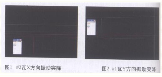
1 Failure phenomena and troubleshooting ll Symptoms The TSI signal suddenly drops and returns to normal display soon after several seconds of maintenance, as shown in Figure I and Figure 2: 
The phenomenon reflected by the above two figures is the sudden drop of bearing vibration signal during the normal operation of the unit, the X direction vibration of #2 watts is reduced from 40.79 um to 2 um, and the vibration of #1 watt Y direction is reduced from 81.35 um to 11 um mutation to maintain 2-3 After seconds return to normal. Check the 3500 module OK lamp display is normal, no report S output. A similar abrupt change has occurred in the axial displacement, high cylinder differential pressure, bearing vibration, and other measurement points, and the occurrence time and amplitude of change have no regularity. There is no large-scale electrical equipment start and stop operation, and the power supply has no abnormal alarm. The common feature is abrupt change direction. Both showed a downward trend.
1.2 Troubleshooting The TS1 system consists of sensors, extension cables, preamplifiers, local cables, and S-test protection systems. Operating environment is high temperature, strong electromagnetic field environment, interference from internal system anomaly (measurement components, devices, etc.) and external environmental factors (conductance coupling, electromagnetic radiation, oil film or vapor excitation, etc.), may cause single-point signal The display is abnormal and even causes the protection to malfunction.
1.2.1 Sensor System The sensor system is composed of probe, extension cable and pre-amplifier. The probe is covered with a shrinkable protective sleeve and is mounted on a rigid support and connected to the prosthesis through a three-layer coaxial cable. The probe can not only perform static (displacement) test, but also can perform dynamic (vibration) measurement. The vibration of the measured object or displacement is converted into voltage signal and sent to the monitoring and protection system for processing. Check points:
(1) The rigidness of the probe holder and the installation should be firm; use the feeler gauge to perform qualitative and quantitative inspection on each S-loop to check the linearity;
(2) Extension cable joints should be locked; joints should be kept clean, leaving oil or water may cause the probe's electrical characteristics to change, resulting in abnormal display; joints can not be in contact with the bearing box, platen, otherwise it will bring serious Interference and measurement errors, even the system does not work properly;
(3) The extension cable insulation sheath shall be not damaged. Once the sheath is damaged, it may cause the circuit to be grounded at multiple points, the signal will be interfered, and the cables in the bearing box will be tied tightly;
(4) The front device box body is well grounded and firmly fixed; the front boring device shall be installed in the tank body and the coaxial cable shall be firmly connected; the three-core terminal shall be firmly connected and the cable shield shall be insulated and floated in the box;
(5) The front device housing should have good shielding measures against electromagnetic interference.
The primary component of the TS1 system is an eddy current probe. The high-frequency oscillating current in the preamplifier flows through the extension cable to the human probe coil to generate an axial magnetic field. When the metal body under test is close to this magnetic field, the magnetic force lines are cut to generate eddy currents. The eddy currents are sent to the front detector for detection and amplification, and converted into a voltage signal that varies with the gap. If an external magnetic field affects the magnetic field generated by the coil during operation, electricity is generated. The size of the vortex does not accurately reflect the gap between the probe and the measured object, causing measurement anomalies. 
1.2.2 The local cable sensor system is connected to the monitoring and protection system through the local cable. Because the cable is in the zone of high temperature and strong electromagnetic interference, once the cable insulation is damaged, the potential difference between different ground networks will be in the shielding layer. The circulation is generated and superimposed on the signal causes fluctuation or abrupt change of the analog signal. The low voltage signal line of the sensor is close to the high voltage line or high magnetic field, and may also cause interference. Local cable troubleshooting points:
(1) The cable must have reliable protection and fire protection measures to ensure that the cable and insulation shield are not damaged;
(2) In order to improve the operational reliability of the TSI system, the cabinet end must be reliably grounded;
(3) The cable must use correct protective measures to suppress interference. For the Bentley 3500 system, the local cable shield must be connected to the shield terminal (SHIELD) on the monitoring and protection system to achieve single-end grounding of the system.
(4) The control cabinet is insulated from the metal and the ground wire is independently led to the thermal control ground. No damage to the cable or abnormal grounding occurred during the inspection of the connection cable.
1.2.3 Monitoring Protection System Monitoring and protection system is divided into hardware and software in two parts: hardware includes dual power modules, frame interface, overspeed, vibration, differential expansion, relay modules, etc.; software includes frame with S software, data acquisition server software, operation Show software.
Hardware part: BENTLY3500 system adopts dual channel design, built-in microprocessor; accepts input of each sensor to meet the needs of online measurement: sensor and loop have continuous self-check device: analog current, alarm switch dry contact output; power module redundancy Additional supply power 24VDC; Software part: The internal settings of various monitoring modules can be connected through the interface of the computer equipped with framework configuration software and the configuration dedicated interface of the framework interface module, through the computer set up a range, alarm, relay channel definition, etc. All parameters are downloaded to each relevant module. Each measured S value can be hardwired to output 4-20mA to the DCS system for further logically configured data display functions.
Check points:
(1) The system power supply should be a high-voltage AC power supply (175~250VAC), using UPS as the main power supply, and the security power supply should be used for the auxiliary power supply. The power supply voltage should not fluctuate significantly;
(2) VT terminal and public COM terminal input -17.5VDC to -26VDC DC voltage signal. The front device needs to provide -24VDC DC voltage signal from the system;
(3) Observe the module indicator: OKLED module should be flashing when working normally; TX/RXLED: used for transmitting and receiving, when this module is in good communication with other modules in the frame, iALARMLED: When the relay channel is in alarm state Flashing
(4) Check the control cabinet terminal wiring, the wiring is firm without looseness, the shielded wire is connected with SHIELD, COM;
(5) Check the software settings, confirm that the range, alarm, and protection settings are correct, and that the bad point removal function in the logic configuration of the relay output module is checked and the protection output delay is correct;
(6) Card output 4~20mA hard wired connection is correct, no looseness;
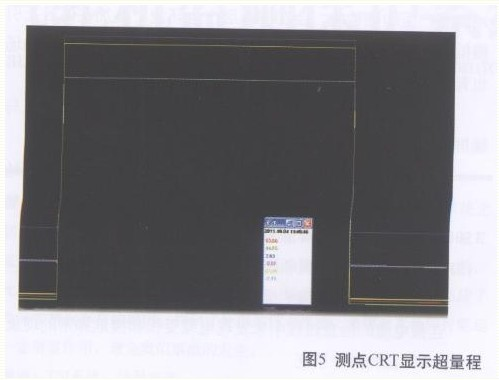
(7) DCS side signal receiving card power supply, communication LED display is normal, channel test without deviation. Check the connection cable for no damage. Figure 5 shows the abnormality of the monitoring signal caused by the failure of the DCS card.
During the operation of the unit, due to the failure of the DCS analog input module, the relevant display measurement points of the module are displayed: axial displacement, differential expansion, and maximum bearing vibration signal (overrange). In order to avoid the big vibration protection of the bearing vibration, it is required to judge the “bad quality†of the measurement point in the logic of the DCS. The over-range measurement point is judged to be a bad point, and the bad point is eliminated. It does not participate in the protection judgment and avoid the protection from misoperation. 
1.2.4 Operation Environment The measurement loop of the system is in the environment of temperature, vibration, and electromagnetic interference, which can easily cause the most signal abnormalities in the measurement.
(1) The magnetic bearing housing, end cover and front device housing should not be attached with magnetic objects. During the operation of the generator set, the walkie-talkie should not be used near the electronic equipment room and the front device housing.
(2) The generator grounding carbon brush shall supervise the electrician to inspect and replace it in time so as to avoid the measurement of the charged interference of the probe holder due to bad grounding of the carbon brush.
(3) The aging of the measuring circuit cable should be inspected regularly. The high ambient temperature or oil corrosion will damage the insulation layer, and it will also cause irregular fluctuation of the measurement signal.
(4) In order to avoid damage to the TS1 card and the front device, it is forbidden to carry out the pressure welding operation near the measuring cabinet.
1.3 Findings After the investigation of the above items, it was found that during the inspection of the sensor system, the cable connection of the front rake was not locked, some looseness occurred, there was a small amount of oil stains on the connection cable joints, and the grease was cleaned and the joint was locked. The mutation disappeared completely and the cause of the mutation was basically confirmed.
2 Failure analysis and summary When the unit with normal load operation, TSI monitoring signals: axis displacement, differential expansion, cylinder expansion, shaft vibration, eccentricity and Watt vibration output parameters, will change the random group load changes slowly, changes in value Not the same, but the trends are generally consistent. The occurrence of TSI system monitoring signals indicating abnormalities is roughly summarized as follows:
(1) The abrupt change of many relevant parameters of the TSI monitoring system: Firstly, compared with the previous operating curve of the unit, similar problems often occur when the unit is under variable load and operating conditions, and they may pay close attention to the development of relevant signals with the professionals. Take the necessary safety measures in time and refrain from escaping protection.
(2) The measurement value at one point of the TSI monitoring system is abrupt, and the change of the measurement point with the same position is not obvious: under the premise of checking the wiring of the measurement channel and the normal operation of the monitoring equipment, the external system caused by external factors such as the axis of separation, environment, etc. resonance. For this kind of situation, the scheme of optimizing the protection setting or protecting the output logic should be adopted, and the principle of “preventing refusal to prevent misoperation†should be adopted to improve the reliability.
(3) Irregular jumps occur in the measured values ​​at a certain point of the TS1 monitoring system, and the interferences (RF interference, low-frequency interference, and multi-point grounding) of the system are analyzed; if the probes are continuously cyclical, the probe and the front should be considered. Whether there is damage to the device, step by step through the root cause of the situation.
Reasonable logic and reliable measurement system environment are the basis, and timely maintenance and maintenance are guaranteed. Specification TSI system equipment installation. Line connection, regular equipment verification, standardized operation and maintenance management and reasonable setting, software configuration design, will greatly improve the system reliability and avoid unit protection misoperation.
3 Concluding remarks In order for the TSI system to accurately reflect the operating status of the set-up and the protection system is working properly, maintenance personnel should be familiar with the measurement principle of the TSI system and be proficient in sensor installation, commissioning and module parameter settings. When the system monitoring parameters are abnormal, based on the experience accumulated in daily maintenance work, the rough cause can be quickly determined and correct measures can be taken to solve the problem.
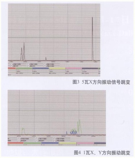
Turbine monitoring and protection system fault analysis and processing Steam turbine is a large and dense machine that rotates at a high speed. Due to the operation state of the unit, component structure, processing and installation, etc., the turbine rotates at a high speed and starts and stops. The continuous monitoring and protection of the unit operating parameters, such as axial displacement, differential expansion, eccentricity, and vibration, is particularly important. In recent decades, some developed countries have developed rapidly in the research of large-scale rotary machinery vibration and other state parameter detection theories, monitoring instruments, and testing technologies. Many products have been serialized and standardized, and are used in large-scale power plant units. For example, Bently, IRD, BEI in the United States, B&K in Denmark, Philips in Germany, Shenke in Japan, Takeichi Takeda in Japan, etc. These brands have long been engaged in the research of reliability, safety, maintainability, and diagnostic equipment for large-scale rotating machinery. Therefore, it has strong data and software strength and its reliability has been universally recognized. Fig. 3 and Fig. 4 are the signal waveforms of the vibration of the bearing under the simulated electromagnetic interference during the shutdown of the unit. Such a large sudden change is enough to cause the unit protection to malfunction. Although the improved RFI/EMI of the 3500 preamplifier has made radiofrequency interference and electromagnetic interference strong enough to meet European electromagnetic compatibility standards, it has been reinstalled to prevent the monitoring signal from being interfered with by strong radio signals according to the site conditions. Li protection box.