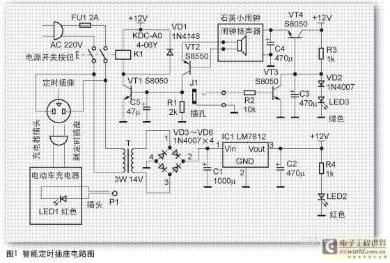
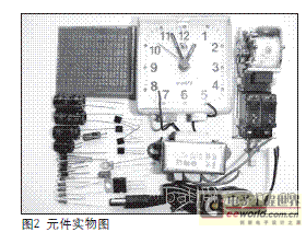
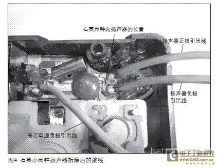
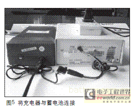
At present, there are two types of design schemes for electric vehicle lead-acid battery chargers on the market: the first type is a two-stage type, that is, constant voltage charging, and the charging current is gradually decreased as the lead-acid battery voltage rises (ie, the charging current is first large). Small), when the lead-acid battery power is replenished to a certain extent, the voltage of the lead-acid battery will also rise to the set value of the charger, the red indicator diode of the charger will be extinguished, the green indicator diode will be lit, and the charger will automatically turn into The second stage of 涓 current float charging; the second type is three-stage, that is, constant current charging, and then constant voltage charging, when the voltage of the lead-acid battery rises to the set value of the charger, the red indicator diode of the charger When it is off, the green indicator diode will light up and the charger will automatically switch to the third stage of the current floating charge. From the above design scheme, it can be known that whether it is two-stage charging or three-stage charging, the final stage is 涓 current floating charging. Practice has proved that the current charging and charging of lead-acid batteries at the appropriate time is not only a further sufficient power, but more importantly, the repair and maintenance of lead-acid batteries to prevent the formation of irreversible sulphation of lead-acid batteries. ". Practice verification, generally 2 to 3 hours of 涓 current floating charge is appropriate, overcharge or insufficient charging will seriously harm the positive plate of lead-acid batteries, greatly shortening the service life of lead-acid batteries. In response to the above charging situation, the author made a simple electric vehicle lead-acid battery charger intelligent timing socket, which can time the current stage of the charger, when the current float reaches the set value. The intelligent timing socket automatically cuts off the charger and its own AC power supply, and ends the charging without having to manually power off. I use the smart timing socket for my own Sendi YBC-48L (14Ah) charger, which is very convenient. Subsequently, the same time socket was designed and manufactured for the chargers of many relatives and friends. Through the use, everyone felt that the service life of the lead-acid battery was prolonged, and the daily power-off of the power was eliminated. First, how does the intelligent timing socket work? The circuit of the intelligent timing socket is shown in Fig. 1. It consists of AC power switch, electromagnetic decoupling coil drive circuit, timing circuit and DC power supply circuit. Plug the circuit into the power plug, press the AC power switch S1 button, turn on the 220V AC power supply and start working. 220V AC power supply through 14V power transformer T step-down, bridge rectifier circuit rectification, filter capacitor C1 filter, three-terminal regulator integrated circuit IC1 regulator, filter capacitor C2 filter to generate a stable +12V DC power supply, the +12V three Road output: (1) Add R4 to LED2 for +12V DC power supply operation indication. (2) After R3, VD2, LED3 series voltage regulation, C3 filter is applied to the base of the voltage regulation adjustment tube VT4, so that VT4 will be regulated to +12V to 2.1V, output by VT4 emitter, and the 2.1V is filtered by C4. Add to the quartz small alarm clock power supply positive and negative poles to provide DC power supply (tips: 2.1V is higher, quartz small alarm clock is slightly faster, the timing value can be 4~5 hours). (3) is applied to the electromagnetic decoupling coil of the switch S1. The 220V AC power supply is added to the charger via the timing socket. When the charger has not been transferred to the floating charge state, the red LED 1 of the charger is illuminated, and the 2V voltage across the LED1 passes through the plug P1, the jack J1, and the resistor. R2 is applied to the base of VT3, VT3 is saturated, and the base of VT4 of 2.1V regulator is short-circuited to ground. The regulator VT4 is cut off. The quartz alarm clock is not supplied with DC power supply. When the charger is turned into 涓During the current floating charge and charge phase, the charger red diode LED1 becomes zero voltage at both ends (the charger green diode emits light), at this time VT3 is also cut off due to the base zero voltage, the power supply regulating tube VT4 is normally turned on, and the output is 2.1. V DC power supply, quartz small alarm clock starts to count, when the timing reaches the preset value, the quartz small alarm clock outputs a low-level audio pulse signal, and the low-level audio pulse signal is filtered by the VT2 amplification and rectification via the capacitor C5. A DC voltage makes the VT1 saturated and conducts, and the electromagnetic decoupling coil of the switch S1 is electrically generated to generate a magnetic force, so that the switch button is unhooked and tripped, and the AC power is disconnected, thereby automatically ending the charging. Second, component selection Component selection, such as the circuit schematic: VT1, VT3, VT4 select S8050 type transistor, VT2 select S8550 type transistor, IC1 selects LM7812, VD1 selects IN4148 type diode, VD2~D6 selects IN4007 type diode, LED1, LED2 selects ordinary red LED, LED3 uses ordinary green LED, R1 selects 2kΩ common resistor, R2 selects 10kΩ common resistor, R3, R4 selects 1kΩ common resistor, switch S1 selects KDC-A01-06Y type, P1 and J1 select ordinary mono Headphone plug, jack. Transformer T selects 3W/14V power transformer, C1 selects 1000μF/25V electrolytic capacitor, C2, C3, C4 selects 470μF/25V electrolytic capacitor, C5 selects 47μF/25V electrolytic capacitor. The physical object is shown in Figure 2. The soldered circuit is shown in Figure 3. Third, the installation and use instructions of intelligent timing socket I use the universal printed board to solder the timing socket circuit. When installing, be sure to remove the small speaker inside the quartz small alarm clock. The small speaker is connected to the VT2 emitter of the triode, and the small speaker is connected to the triode VT2. Base, lead is shown in Figure 4. The timing socket circuit that I soldered into is connected to the charger as shown in Figure 5. Before charging, set the timing value first, connect the charger control signal output plug P1 and the timing control signal to the jack J1, connect the charger to the battery, plug in the AC power plug, and finally press the switch S1 button. The smart timing socket will automatically start timing when the charger is transferred to the floating charge state and end charging when the timing value is reached. When the charger cannot be transferred to the floating charge state due to a problem with the battery (such as excessive water loss), disconnect the charger J1 between the charger plug P1 and the timing socket, and the timing socket is energized to start timing. The charging is automatically ended when it is reached. Shark Fork,Shark Tank Ifork,Ifork Shark Tank,Shark Pliers TAIXING HAITAI GLOBAL TRADE CO.,LTD , https://www.jshaitship.com


Lead-acid batteries have low cost, mature technology, stable performance, abundant raw material sources and high lead recovery rate, which are the first choice of electric vehicle manufacturers. The chargers corresponding to lead-acid batteries also prosper in the market.