DURA Automotive Systems is a global automotive supplier specializing in the design, engineering, and manufacturing of solutions that drive the evolution of mobility. With a legacy comprising more than 100 years of inspired invention, the company is recognized by leading vehicle manufacturers as the preferred supplier partner for innovative, highly integrated, mechatronic systems, and lightweight solutions. (Source: https://www.duraauto.com/) The product is a window encapsulation with three different part inserts: transparent glass, glass run channel (GRC), and small aluminum insert. The deformation of the GRC made the part unable to meet the gap and flush requirement, leading to difficulties in the assembling process. DURA Automotive engineers used Moldex3D to identify the root cause of the deformation, and they found out that the thick PVC wall in contact with the GRC led to this functionality failure. Therefore, they applied ABS insert to reduce the thick region without compromising part stiffness. As a result, DURA was able to effectively find the optimized design and decide to modify the tool according to Moldex3D results in order to reduce warpage and solve the assembling problem. DURA utilized Moldex3D to verify the modified design of a glass run channel to solve warpage, cooling and sink mark problems. DURA had to meet the gap and flush requirement of a window encapsulation. The part is composed of different part inserts including transparent glass, aluminum glass run channel and small aluminum insert. These three inserts are over-molded with PVC materials (Fig. 1, 2). To meet the assembly requirement, DURA could not compromise the massive thickness at the near glass run channel even though it is the cause of deformation. However, the GRC part was getting a 5 mm deflection along the X direction due to uneven shrinkage and cooling. (Fig. 3). Therefore, the GRC part failed to meet the gap and flush requirement and that led to difficulties in the assembly process. Moldex3D helped DURA analyze and correlate the existing problems to find out the reason for GRC deflection (Fig. 4). Moldex3D helped to analyze and find out the reasons behind the warpage. The simulation results showed that the high variation of the wall thickness near the GRC area (Fig. 5), high shrinkage owing to the accumulated hot spot (Fig. 6), non-uniform volumetric shrinkage, and insufficient cooling time led to this problem. They also found sink marks at the end of cooling (Fig. 7). After running a couple of iterations to modify the process conditions to reduce deformation, DURA still could not able to meet the gap and flush requirement. Thus, they decided to place an ABS insert at the without compromising thickness and part strength (Fig. 8 & 9). DURA also utilized Moldex3D to validate their design changes. As a result, DURA was able to effectively reduce warpage (Fig. 10 & 11) and successfully solve the assembling problem. They also significantly reduced the cooling time from 112 sec to 38 sec (Fig. 12 & 13)and eliminated the sink marks (Fig. 14). DURA CFT team utilized Moldex3D to verify the design modification and found the GRC thickness can be reduced by 85% without compromising the part stiffness. As a result, they have identified the root cause and verified that the modified design could help reduce warpage, sink marks and cooling time (Table 1). Camping Fridges Cooler VIP,Food Camping Cooler Container,Beverage Cold Chilled Cooler Nantong Ecotherm Insulations Co., Ltd , https://www.vactherm-insulation.com

Summary
Challenges
Solutions
Benefits
Case Study
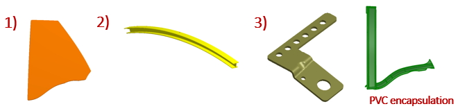
Fig. 1 Encapsulation assembly designed with (1) transparent glass, (2) glass run channel and (3) aluminum insert.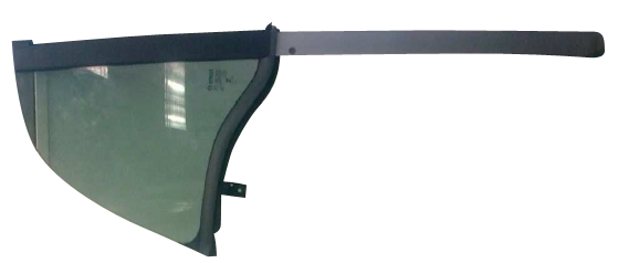
Fig. 2 Physical assembly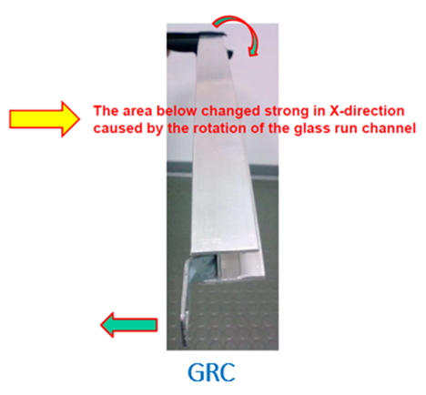
Fig. 3 The GRC deformation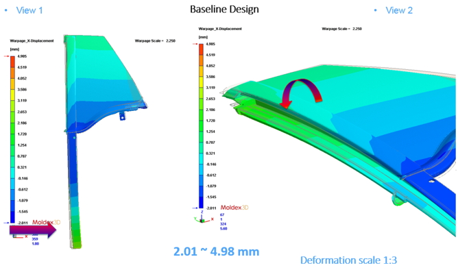
Fig. 4 Moldex3D Warpage result has captured the GRC deformed 5mm in the X-direction.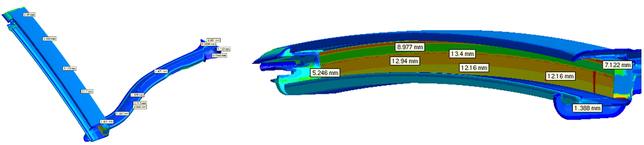
Fig. 5 There are varying thicknesses of the part. The maximum thickness is 13.4 mm and the minimum thickness is 0.5 mm.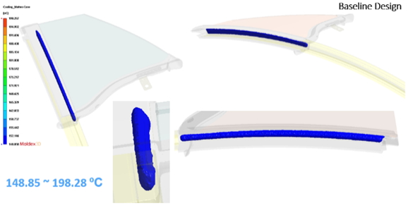
Fig. 6 The iso-surface of the plastic melt-zone showed that the part still has a molten core after the cooling cycle.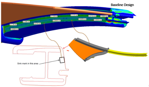
Fig. 7 The maximum sink mark depth was around 0.1 mm at the end of cooling.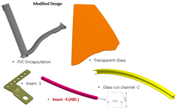
Fig. 8 The modified design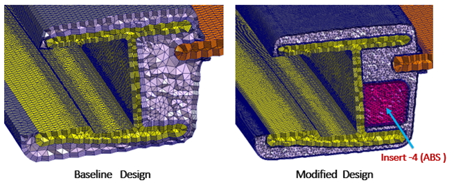
Fig. 9 The baseline design and modified design with an ABS insert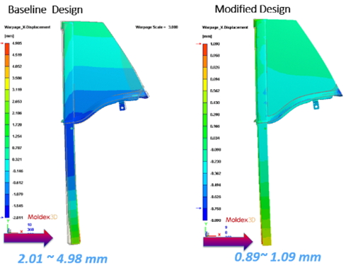
Fig. 10 In the modified design, the X-axis has been reduced from 5 mm to 1 mm.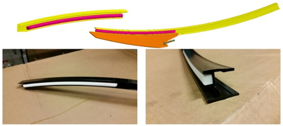
Fig. 11 The actual product of the GRC with ABS insert showed that after placing the ABS insert, the X-axis displacement has been reduced to 1 mm.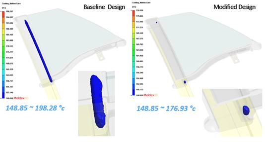
Fig. 12 The iso-surface of the plastic melt zone showed that the melt core has been improved after adding the ABS Insert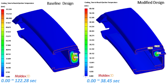
Fig. 13 The required cooling time has been reduced after adding an ABS Insert. It only took 35 to 40 seconds to reach the ejection temperature for the modified design.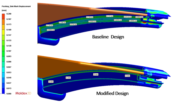
Fig. 14 The sink mark displacement has been decreased from 0.1 mm to 0 mmResults
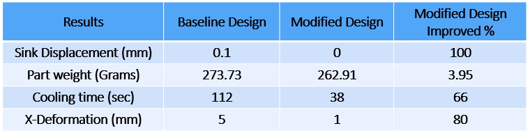
Table 1 The comparison of the baseline and modified design
Customer Profile